Projects
A selection of systems work spanning the Linux device-driver stack, RISC-V board bring-up, RTOS firmware, and protocol decoding. The write-ups below focus on the kernel-level engineering — device tree, the GPIO and SPI subsystems, interrupt routing, and driver instrumentation — rather than the end product.
A1 — Linux-Based Smart Meter Gateway (RISC-V Driver Bring-Up)
Brought a Wi-Fi/BLE network device driver up on a non-reference RISC-V platform: the BeagleV-Fire (Microchip PolarFire SoC). Ported Espressif's ESP-Hosted driver — which treats an ESP32-C6 as the Linux host's radio over SPI — from its Raspberry Pi origins to a board with an FPGA-routed SPI bus, landing a real wlan0 interface backed by the kernel's cfg80211 subsystem. Separately patched the in-tree option.ko USB serial driver to bind the SIM7080G cellular modem for NB-IoT.
Full Technical Breakdown
Objective
ESP-Hosted lets a Linux host offload its wireless stack to an ESP32, carrying 802.11 frames over SPI with two out-of-band GPIO signals (handshake and data-ready). The driver was written, tested, and documented exclusively against the Raspberry Pi. The goal was a working wlan0 on the BeagleV-Fire that could scan, associate, and route traffic — which meant debugging every layer of the Linux device model on a board the driver had never seen.
Device tree: resolving a chip-select conflict
The first insmod failed with spi spi0.0: chipselect 0 already in use. The base DTS instantiated a placeholder SPI device (compatible = "rohm,dh2228fv", the well-known spidev stand-in) that claimed CS0 before the driver's spi_new_device() could register its own. The fix was to remove the offending child node from the SPI controller, recompile the DTS with dtc, and install the new DTB — keeping a golden copy aside after one in-place edit dropped the board to a bare U-Boot prompt.
spi@20108000 {
    compatible = "microchip,mpfs-spi";
    esp32_spi@0 {                      /* ← removed: it squats on CS0 */
        compatible = "rohm,dh2228fv";
        reg = <0>;
    };
};
GPIO subsystem: per-controller line numbering
The driver hard-coded Raspberry Pi BCM numbers (e.g. GPIO 22). On the BeagleV-Fire, gpiolib allocates line numbers dynamically — the six gpiochips start at 512, so GPIO 22 simply does not exist (the request returned -EPROBE_DEFER). I read the live mapping from /sys/kernel/debug/gpio and remapped the handshake and data-ready signals to the actual line numbers behind the physical header pins.
Interrupt routing: not every gpiochip is IRQ-capable
With valid line numbers the GPIO request succeeded, but requesting an interrupt returned -EINVAL. Cross-referencing /proc/interrupts showed only the SoC's MPFS GPIO controller (gpiochip2) registers an interrupt parent; the FPGA-fabric COREGPIO controllers can do level I/O but expose no irqchip. Moving the handshake/data-ready lines onto gpiochip2 let request_irq() succeed — the IRQs then incremented on every ESP transaction.
Driver instrumentation & signal-integrity debugging
The IRQs fired but no netdev registered — the protocol handshake never completed. I instrumented esp_spi_work() with a print_hex_dump() of the RX buffer right after spi_sync_transfer(), gated at KERN_ERR so it surfaced regardless of the driver's verbosity. The dump turned a guessing game into a decision tree: all-0xFF meant MISO was floating; structured-but-corrupted bytes meant a signal-integrity / clock problem rather than a SPI mode mismatch.
rx: 00000000: ff ff ff ff ff ff ff ff ...   /* MISO floating  */
rx: 00000000: 01 80 00 00 0f 80 06 00 ...   /* framed but corrupt → SI/clock */
SPI clock negotiation in the driver
At the ESP-Hosted default of 10 MHz the flying-lead wiring mis-sampled bits; worse, the ESP firmware renegotiates the bus up to 26 MHz mid-boot, which the wiring could not sustain — the interface-init command timed out every time. I patched adjust_spi_clock() to clamp any requested rate to a value the link could actually hold, refusing the renegotiation rather than complying with it.
static void adjust_spi_clock(u8 spi_clk_mhz)
{
    if (spi_clk_mhz > SPI_INITIAL_CLK_MHZ)   /* refuse the 26 MHz bump */
        spi_clk_mhz = SPI_INITIAL_CLK_MHZ;
    ...
    spi_context.esp_spi_dev->max_speed_hz = spi_clk_mhz * NUMBER_1M;
}
USB serial: patching option.ko for the SIM7080G
For the cellular side I built the in-tree option USB serial driver from source and modified it to claim the SIM7080G modem's interfaces, exposing the AT-command ttyUSB ports so NB-IoT sessions could be driven from Python on the host.
Result
After capping the clock the boot sequence completed and wlan0 registered with the ESP32-C6's MAC. With eth0 forced down, ping returned steady replies — every packet travelling host → SPI → ESP32-C6 → Wi-Fi. The full path was exercised end to end, from the cfg80211 wireless subsystem down to bit timing on the physical wire.
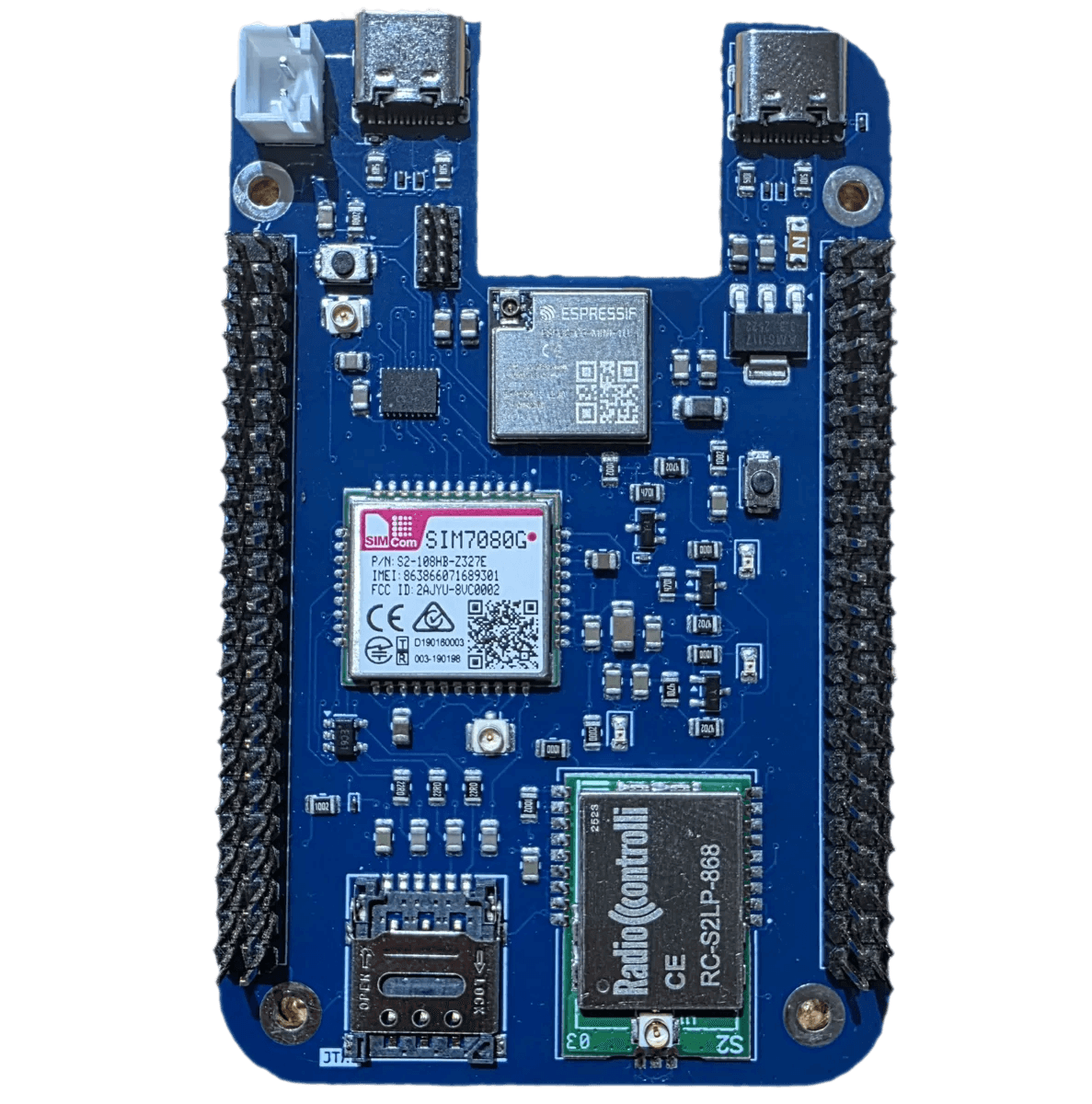
A0 Cape
A0 — ZephyrOS-based Smart Meter Gateway
A custom-designed Zephyr RTOS-based smart meter gateway built around the ESP32-C6, with onboard NB-IoT and wireless M-Bus modules for meter data collection, pin-compatible with the BeagleV-Fire so it can also act as the A1 cape. Paired with the A0 Baseboard, which supplies regulated power, adds Ethernet and an SD-card interface for local logging, and integrates the TSS721ADR wired M-Bus transceiver.
Full Technical Breakdown
Why it matters for kernel work
Zephyr shares the same configuration idioms as the upstream Linux kernel — a devicetree describes the hardware, Kconfig gates the build, and peripherals are reached through subsystem driver APIs. A0 was a ground-up board where I owned both the schematic and the firmware, which meant writing the devicetree overlays and binding the on-board peripherals to their drivers rather than inheriting a working board definition.
Hardware & integration
Designed the main board and companion baseboard in KiCad: regulated power rails, an ESP32-C6 host, NB-IoT and wireless M-Bus radios, the TSS721ADR wired M-Bus front end, Ethernet, and an SD-card slot for local logging. The board is deliberately pin-compatible with the BeagleV-Fire so the same hardware doubles as the A1 Linux cape — one PCB feeding two software stacks (Zephyr on A0, Linux on A1).
Firmware
Brought up the peripherals under Zephyr: configuring buses in devicetree, enabling the relevant subsystems through Kconfig, and wiring the metering radios into the data path so collected readings could be forwarded upstream over NB-IoT.
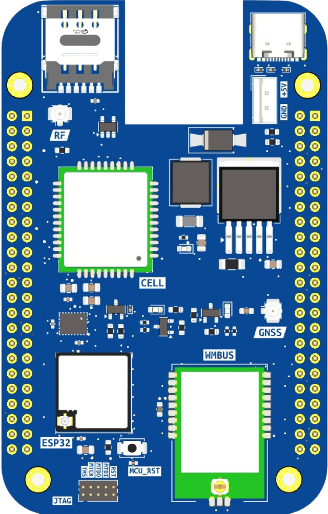
A0 Main Board — 3D Render
Rocket Flight Computer — Nakuja Project
Designed and built two custom flight computers for the Nakuja rocketry project. Both feature the ESP32 with a BMP180 barometer, MPU6050 IMU, GPS, pyrotechnic ejection channels, and LiPo power management. The first variant transmits real-time telemetry over WiFi, the second over LoRa at 433 MHz — for which I also designed a 433 MHz Yagi-Uda antenna for the ground station.
Full Technical Breakdown
Low-level systems relevance
The flight computer is bare-metal-adjacent embedded work: integrating multiple sensors over I²C and SPI, servicing them within a real-time budget, and moving sampled data off-board reliably under vibration and power transients. It is where I first worked directly against peripheral registers and timing constraints — the same instincts that later carried into driver debugging.
What I built
Two PCB revisions in KiCad carrying an ESP32, BMP180 barometric sensor, MPU6050 IMU, and GPS, plus a power-distribution and ejection board driving the pyrotechnic recovery channels off LiPo power. One build streamed telemetry over WiFi; the other over a 433 MHz LoRa link, paired with a directional Yagi-Uda antenna I designed for long-range reception at the ground base station.
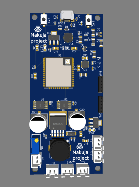
WiFi Flight Computer — Front
Smart Water Meter Data Parser
A Lua parser that decrypts and decodes encrypted wireless M-Bus frames from smart water meters using AES-128, extracting meter readings and consumption data. Validated against the Sharky 774, Axioma, Sontex 566, Supercal 539, and Euris 2.
Full Technical Breakdown
Relevance
Decoding wireless M-Bus is exactly the kind of byte-exact, spec-driven binary parsing that the receive path of a device driver demands: walking a framed wire format field by field, decrypting the payload with AES-128, and rejecting malformed frames rather than trusting their length headers. The driver work on A1 — where corrupted SPI frames had to be told apart from valid ones by their byte signature — drew on the same discipline.
What it does
Parses encrypted wM-Bus telegrams from a range of commercial meters, performs AES-128 decryption, and extracts consumption readings into a normalised form. Tested across five meter families with differing frame layouts.